Wednesday 28 September 2016

Future City: Update 6 - A Balancing Act

Industrial Zone

Using the previous steel structure procedures and some new bits and pieces I've been building a few elements for populating the industrial areas of the city.  For now we have:
  • Warehouse or factory building, with roof-top windows/solar panels, and chimneys.
  • Round storage silo or tank, with and without steel support structure around it.
  • Simple tower based on the steel-work structures.
  • Simple chimney of a couple of different styles.
Structures for first-pass industrial zone
During the creation of these, I've been regularly checking the look of the city.  I was pleased with the initial appearance and the variety and layout was working well giving a good view.
Structures in use throughout the industrial districts.

A Recurring Problem

As more elements and more detail were added, holes in the industrial blocks often appeared.
A hole in the industrial zone
This is an indicator of a procedure synthesis running out of buffer space, due to either too much geometry (triangles/lines) or too much calculation (procedure depth/complexity).  To find the problem procedure a bit of digging using the view diagnostics panel is required thus:
  1. Set render depth to show only the tier with the problem in.
  2. Turn on octree node display.
  3. Set octree node depth to match render depth selected above.
  4. Set the node highlight to the node surrounding the problem area.
First stage of diagnosis; what is the error?
This should show up the actual error message (stat shows first error message under node).  To see exactly what happened during the synthesis of this model we can perform these further steps:
  1. Open the engine dev panel to show the synthesis monitoring panel.
  2. Switch on node model filtering to only render models under this node.
  3. Set the model select to only render the problem model.
  4. Request synth analysis graph generation (triggers re-synth).
Second stage of diagnosis; which exact model?
This will re-synthesise the model (shown in the synth panel) so we can look at the output stats in more detail.
Third stage of diagnosis; what sort of memory did we run out of?
From this we can see that we are running out of parameter buffer (abbreviated to 'Control' here), the memory used for all the information flowing between and through the procedures as the calculations are performed.  This will be because the city block sub-division is quite demanding due to there being quite a depth to the process between the top level of the city at which we are starting and where we actually start to generate geometry.

Turning Up The Heat

Hitting these problems has left me feeling a bit in the dark about how well the system is performing in general, how close we are to having them happen again else-where, and where else we may need to improve the procedures building our scene.  It is a balancing act fitting the design and requirements into the resources available (as is often the case), but this is going to be a common workflow occurrence and we need more tools to help us monitor the situation as we work.
A visualisation tool often used for assessing the overall level of something and getting a good feel of how some value varies across a space is a heat-map.
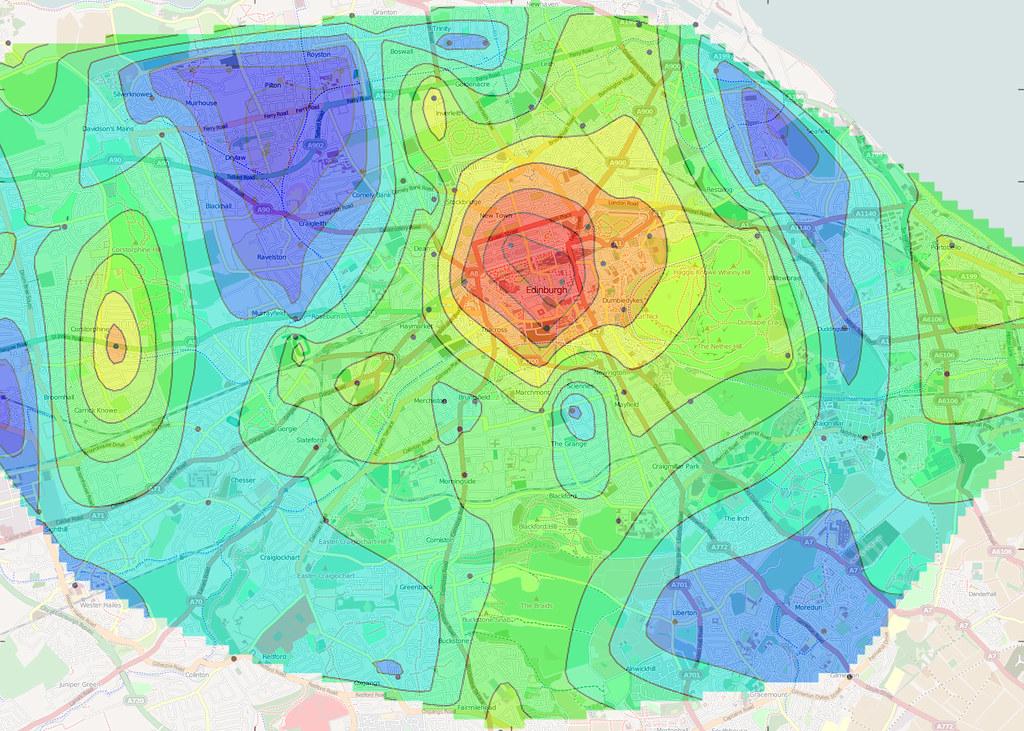
An example of a heat-map
There are many metrics we could benefit from being able to visualise such as:
  • Rendering cost (triangle count, draw calls, materials)
  • Memory use (system memory, GPU memory, synthesis buffer)
  • Synthesis cost (time/cycles taken, buffer use)
  • Measures of complexity (synth depth, stack use, passes generated, analysis, refinement level)
  • Scene complexity (octree nodes, model counts, mesh counts, node status)
All of these help us assess the overall cost and effectiveness of the procedures creating our world.
Some support work was required to capture the statistics needed from the synthesis process, and propagate it through to the rendering stage (with the meshes). Plus, because the output of synthesis is often merged into single meshes, we also needed a way to render parts of meshes separately to give per-procedure colourising.
Various heat-map modes: Triangles, Cost, Time, Stack, Depth
Each new display mode has its own scale configuration setting so that the range of values being visualised in the scene can be seen in the most detail by spreading them across the full colour gradient.
Gradient scaling settings for each heat-map mode
By also having a distinct colour for a 'maxed-out' value, i.e. on or above the scale setting we can interactively measure the value on a particular element in the scene by dialling the value up and down until we are on the changeover point between being the top end of the gradient and the highlight colour.
I'm not 100% happy with the choice of colour gradient, but full spectrum gradients (which I assumed would be best) seem more suited to continuous functions and not the more random patterns we get here.  Instead I'm trying a simpler black-blue-cyan-white 'icy' gradient, with red for out-of-range values (above the chosen scale setting).

Hot In The City

Testing these display modes out on Future City as a whole shows that we are actually in a pretty good position with fairly low quantities of geometry and no hot-spots that really stand out as problematic.
Triangle counts visualised across detail levels.  Only a few hot-spots at around 7,500 triangles.
It looks like we can actually afford a fair bit more geometry and detail, but at the moment we can't afford synthesis cost (hence the holes).
Typical synth stats for chunk of the city.  Scope for a re-balance I think.
In the upper (distant) tiers most models are in 5,000 to 10,000 triangle range, and the lower tiers are at about 1,500 to 3,000 triangle range, which is pretty low for assets these days, with the overall GPU memory at about 100MB with the viewpoint in the centre of the city.  The draw-calls are moderately high at about 1,000 but this shouldn't change much as more detail is added and can be improved in other ways later on (I'm not doing a frustum cull yet for example!).
So, we need to reduce the synthesis cost.  There are a couple of ways we could go here:
  1. Reduce the complexity of some of the more complex procedures, for example we could convert our super-splitter procedure (see last weeks post [link]) into an operator.
  2. We can re-balance the way each synthesiser's buffer is allocated so there is more parameter space available (and less geometry space).
  3. We can look at one of the several planned optimisation passes on the synthesis processing and evaluation itself.
  4. Other ways?  (there are always other ways).
At the moment I think it is a bit premature to bake the Splitter proc into a procedure as we lose the ability to live edit and continue to improve it (much slower turnaround).  Some investigation of the usage of buffer memory would be helpful in deciding on a new parameter/geometry split for the buffers, perhaps with a buffer use heat-map mode?  I didn't want to get into optimising the synth system yet as I think I can get more elsewhere first and it's tricky work.

Hot-line

I did do some work simplifying the steel tower procedure, which seemed particularly bad, using line primitives (which I have so-far not needed).  In the far distance, the steel beams reduce down to 8 triangles each, but this seemed too much so I added an extra detail switch to a single line segment.  This helped the geometric/visual detail level, but didn't  help the synthesis complexity as we were still having to sub-divide down a lot to get to the individual girders.  Instead of relying on these line based beams I remembered I had a line grid primitive (originally used to draw the ground-plane grid) and so switched this in at a higher level for the steel-work side sections.  Thus each tower is now made of four grid primitives in the distance.  I took this a stage further by double the grid cell size progressively too as I noticed that the fixed width (screen space) line rendering becomes a solid block when the tower is really small.  This helps keep it looking thinned out and again reduces the render cost.
Reduction in tower complexity at lower detail levels by use of line (grid) primitive.

Late Night Ideas

One night last week I couldn't sleep for thinking about these problems and an enticing thought occurred to me about how I can neatly improve this synthesis depth/complexity problem by an order of magnitude and allow lots more detail for the distant city.  This will help a lot for aerial views of the city where you should be able to see a huge amount of small detail when at a considerable distance (probably the worst case scenario).  I think I'm going to explore this next after playing with the synthesis memory balancing.  More details next time… maybe…

Sunday 18 September 2016

Future City: Update 5 - The Fencepost Problem

Fence-posts

A lot of structures have a regularity to them that is useful to emulate, whether it be fences, walls, windows, rows of houses, tree, or chimney pots.  As with the fence-post problem you can't implement them as a straight repeat of a single object though since you need one more post than fence panels.
The Fence-post Problem: N panels but N+1 posts.
Before we look at solving this however, we will start simpler; looking at how we can handle instancing of the more-straightforward repeating structures.
Example of a simple array of objects.

Recursion

Apparance doesn't yet support arrays as a data-type, arraying of objects, or any form of looping, but an effective alternative that is supported well is recursion.  Here we can break down a repeating problem into successive; sub-division, geometry instantiation, and recursion, until the space is filled.
Basic recursion used for repeating geometry.
The process of split+generate is invoked on the left split area each time until there is no more to split.
The process of sub-division can be improved somewhat in a couple of ways; first, instead of creating a chain of recursions, one-deeper-per-instance, we can tackle it with successive sub-division and two recursion paths instead.  This reduces the stack depth needed from N to log2 N (or thereabouts).
Improved recursion used for repeating geometry.
Recursion is applied to both parts of a central split until there is no more to split.
The other thing we can do is to wrap up the splitting calculations into helper procedures that make it easier to implement these arrays of objects.  The general problem here is that we need to be able to have our own geometry within the recursion process which is tricky to support.  Instead of having to support embedding of procedures (akin to passing function pointers in code) however, we can provide two procedures, with which we 'book-end' our own geometry generation.  These handle the Splitting Logic, and the Combining Logic needed to implement the array process. The general form for this is:
Layout of a procedure for arraying geometry using the two helper procedures to wrap the recursion and geometry instantiation.
NOTES: Any external parameters the procedure needs (to customise the generation have to be passed down to the recursion calls too.  The Control channel is used to select which of the three outputs are to be combined before returning to the outer procedure, this could be a pair of recursions, or some generated geometry.  A further improvement to this process might be to use all three at once when an odd number of elements are present since we can make the splitting even by immediately instantiating geometry for the centre region.s
Potential further improvement to recursion efficiency.

The Divider

These helper procedures I've named 'The Divider' as it divides up space in one direction into equal size pieces for our procedure to build geometry into.
Basic recursion helper procedure: The Divider (splitting part)
This is used in conjunction with a 'Merger' which handles aggregation of the elements.
Basic recursion helper procedure: The Divider (merge part)
This is a really useful tool to building and distributing content around the world.  For example, when a long thin strip of land is encountered in the business district, multiple buildings are placed in a row instead of a single long thin building.  Here we see the Divider and Merge stages in use in the Business Block procedure that handles this:
Divider approach used to create rows of buildings in the business district.
And here it is in action as the space available changes.
Array of buildings filling a narrow strip of land using the recursive Divider approach.

The Stacker

To tackle the fence-post problem, and some of the more sophisticated use-cases, a significantly more powerful version of the divider approach is needed.  Here are a couple of examples:
This piece of railing can be sectioned up in a couple of ways, either as the classic fence-post arrangement (circular design 'panels' between flower 'posts'), or by treating the flowers a separators between the circular parts and two end pieces connecting to the walls.
These railings can be divided up in a couple of ways.
This building facade can similarly be broken up in to ways, but these are a bit more involved:
This building facade can be divided up in a couple of ways.
Here, however we divide it up we have two end-caps (the corners of the building), but the way the wall/windows are divided up can be approached in two ways:
  1. The window sections are wider and include a bit of wall.
  2. The wall sections are much cleaner and are present between the end caps and the windows as well as between pairs of window sections.
These requirements can be generalised into the following (optional) sections with what I'm calling 'The Stacker':
  1. Start cap
  2. Multiple repetitions of:
    1. Spacer
    2. Object
  3. Spacer
  4. End cap
This can be constructed in a similar fashion to the Divider, but with more user supplied elements in between the helper procedures.  This happened to turn out to be the most complicated procedure I'd ever built!  I actually tried to tackle this problem a while ago, but decided that it would be impossible without the grouping and notation feature so I set about adding that instead.  I'm glad I did now as notes are used extensively to partition the logic and document the processing involved:
The most complex procedure I've created: 'The Stacker' (splitting part)
This isn't the most efficient implementation, nor the simplest, I'm sure.  But it works, and can be revisited later if it needs speeding up or reducing in size.  I could even be re-implemented in code as a build-in operator if needed.
As with the Divider, there is a corresponding re-combination procedure seen here:
Much simpler companion to The Stacker; the merge part.
As this was a very complicated procedure, and with many combinations of inputs and options it was imperative to have good test cases.  Here we see a large set of instances for most of the various configurations it supports.
Test cases for The Stacker.  Many combinations of the various configurations are tested in one place for easy visual inspection.

Examples

Now we have this powerful tool at our disposal I had a chance to explore what can be done with it.

Wall

A straightforward test case is a wall with regular support pillars and larger end columns.
The Stacker used to implement a wall with regular support and end detail.
Wrapping the different wall elements in a Stacker and corresponding combiner gives us this procedure:
Interesting brick wall structure implemented with the Stacker recursion helper procedures.
Which produces this satisfactory construction.
Wall design constant parameterisation.
Brick Wall procedure expanding to use the space available.

Steel Truss

One of the real test cases I wanted to try out was to build steel-work structures out of girders that can be used as support structures around many industrial components.
Steel structures of the kind I'd like to use in the industrial district of Future City.
More specifically, I want to re-create this configuration:
Example of steel beam configuration I want to produce.
This is made from steel I-Beam sections and has two stacking aspects to it, horizontally we have:
  1. (optional) End upright
  2. Set of cross-members
    1. separated by uprights
  3. (optional) End upright
Vertically the cross-members are stacked thus:
  1. Cross-members
    1. Separated by gaps
This was implemented with a pair of nested procedures, one for horizontal, one for vertical, all contained within a main entry-point procedure.
Nested horizontal and vertical stacking procedures to create steel-work side wall.
Here is a selection of constructs built using this set of procedures:
Random structure variation based around truss, tower, and side procedures.
Steel constructs based around a steel-work side section.
Truss or gantry built from girders.
Close of up construction detail.  As you get closer, the bolts are revealed.

Next

Next I should be able to start building some more interesting structures for the industrial district using all these new-found constructional powers.

Monday 12 September 2016

Future City: Update 4 - Down To Business

This week I've been developing the business district layout a bit, dealing with a few bugs, experimenting with gradients, optimising the rendering, and adding a few features and fixes to help diagnose problems.  Oh, and it was my birthday too :)

Business

The business district is going to be lots of tall, close-packed skyscrapers with occasional open spaces amongst them.  With the area we are covering there are going to be a lot of buildings, and a lot of geometry.  To deal with this we have to introduce the buildings (and gradually higher detailed versions of them) progressively as we get closer.  Since a 'Manhattan skyline' area of a city tends to be visible from a long way off we are going to have to introduce buildings from quite a distance away.  We can do this gradually, and as long as there are some of the tallest ones appearing early on we should get a good impression of a distant city.
Distant 'Manhattan skyline' effect from larger buildings
At the moment we will just use a simple boxy model for the buildings, which should suffice for distant buildings, but will need to be replaced for the closer ones.  The detail testing/switching logic for the skyscraper uses the building height to judge which detail band they should go in.  I set it up to introduce the tallest ones in a large/distant range, the mid-height ones in the next one and the smallest ones in the closer range.  The small ones can be left until quite close before we even fade them in.  Once the viewpoint is within the city, most of what you should be able to see has been faded in.
Inner city, all building proxies faded in.
Most business district blocks are of a size suitable to house a single building.  If they are a bit long or large still we sub-divide a little more and instantiate a couple of similar buildings.
At the moment we will ignore the connectivity and access situation at the periphery of each block that we saw set up in previous posts.  It's not that we aren't going to use this information eventually, but barriers and division are probably not a big features in a business area.  To postpone this for now I added a periphery clearance space around the edge of each block.  This can be later be filled with open-space furniture (benches, water features, trees, etc).  These will carry the open space blocks in the city in amongst the buildings too.
Clearance around buildings connects with open areas.

Detail Comparison

It proved quite tricky to get my head around how to get the building reveal/distance calculations to work in such a way that it was clear what the effects of the control parameters were.  Sometimes it's very easy to set something up like this and then just 'give up' by randomly fiddling with values until it seems to be working well enough.  The first attempt was like this; the values were too arbitrary and I wasn't sure what effect they were actually having.  By stepping back, thinking about the problem in a slightly different way I ended up with a system that works.  The problem was that we have two values with different meanings to compare; the height of the building and the size of the block they are being instantiated into.  Instead of trying to massage one into the 'space' of the other it is easier to convert both into an intermediate, neutral range.  Turning both into a normalised 0 to 1 range and then comparing them seems easier to calculate and balance.
When should we introduce a distance building?
Since the block size are powers of two, it also seemed a good idea to changing them to a linear value for the purposes of comparison too.  This produced the following stages of building reveal.
Stages of distance skyscraper population, far to near.

Gradient Surfaces

Using a simple box for each building quickly blocked refinement as a geometry from a normal box primitive can't be sub-divided automatically.  This has been fixed before by using the generic rectangular patch procedure (see previous post) which sub-divides and adds some interesting extra surface detail.  Since this is a bit 'blocky' I decided to try to implement a smoother version.
Block vs. Smooth surface patch procedure
Until now, all modelling primitives have only supported painting in a single flat colour (all models use vertex colour to drive their diffuse appearance), so to introduce smoother, gradient based surfaces we need another primitive or paint operator.  I decided that a flat rectangular sheet primitive with corner colour inputs would serve best to keep the amount of pre-processing and complex painting around it in the procedure to a minimum.
Coloured Sheet primitive for creating smooth gradient surfaces
Similar to the generic patch, we will be introducing variations in the colouring as the sub-division happens to add detail.  This time however, it's a bit more complicated as the adjacent pieces need to share colours along their boundaries.  Also, we aren't going to vary a single colour, we are going to blend between two main colours as this helps keep the colours consistent as we divide deeper.  By carrying both a blend factor and a seed value with each corner vertex down through the sub-division process we can ensure that as each edge is divided up and perturbed by the same amount from each side.  We end up with a variation on the mid-point noise algorithm and build up a nice surface detail as we get close.
Increasing sub-divisions of smooth patch procedure (high contrast detail setting)
This provides us with a couple of nice features when applied to the buildings:
  • More interesting surfaces (not just flat).
  • Fewer edges visible, less blocky
  • Even the lowest detail buildings have gentle gradients across them.
Smooth patch applied to low-detail skyscrapers in business district.

Summary

This gives us low-ish detail city buildings, which we will re-visit in the future to fully detail and flesh out.  For now though we are going to look at other district types and get them up to a similar level of detail.
This example demonstrates a couple of significant advantage of the procedural approach to modelling:
  1. Re-visiting models to add detail later is a normal part of the process.
  2. Upgrading fundamental elements used across your environment will automatically be applied everywhere it is used.
  3. Building up your scene breadth first instead of having to work depth first means your scene builds up as a whole, and not piece by piece.
  4. You get a working environment sooner, game-play and other disciplines can get to work earlier while the detail is added in parallel.
We shall see these points come up again and again.  They are some of the reasons I like this approach to content creation.

Next

I might do a side-post on the debugging and diagnosis issues I've had this week, but then it's on to the industrial zone!  ..which sounds like something from the Crystal Maze :D

P.S. Cake

Since it was my birthday I thought I'd build some procedural cakes to celebrate.  I'm quite pleased with the result of a day of 'baking'.
Procedural cakes to celebrate.

Monday 5 September 2016

Future City: Update 3 - Blocks & Detail

Blocking Out

After digging down through the zones and district types, we have some large city regions set out.  We now want to break them down into city blocks so that we can start looking at where buildings will go.
The process is similar to the zone sub-division and uses most of the same process and procedures, but this time the design constants are dependent on the district type.  For example: residential and leisure areas are probably in smaller blocks than industrial and space-port blocks, with business somewhere in the middle.  We can experiment with other differences later on, say, favouring longer thinner leisure areas for parks or squarer business areas suitable for skyscrapers.
Block design constants, parameterised by district type

Whitebox

For testing purposes I added a simple cuboid as a placeholder building to each block.
Simple white-box building added to each block for test purposes
This is just a proportion of block size for now, with the height chosen randomly.  In reality a block may eventually have multiple buildings, but for now I just wanted to get a feel for how the city would look and investigate the detail levels at different distances.
View across 'white-box city'

Detail

Apparance is built around the premise of bands of detail extending out from the viewpoint, each higher detail one built based on re-synthesising the lower detail procedures.  As we start to build more detail into the city we need to begin setting up the integration with the detail management in the engine.  Since each re-synthesis is performed using sub-procedures with exactly the same input parameters, something else must provide the ability to change their behaviour as different detail results are required.
Re-synthesis of procedures for successive depths in the detail hierarchy.  How do they know what detail level to generate?
As the scene is progressively refined to give more detail, the blocks the world is divided up into get smaller.  It is this that a procedure can check to decide what level of detail to generate itself at.
For our city blocks we will switch between an extremely low detail (flat) rendition for far in the distance, to our normal block procedure as their size decreases.  This will have the effect of gradually populating the area with more buildings as we get closer.
Switching out the blocks in the distance for a simpler representation.
The normal blocks intercepted and replaced depending on our detail hierarchy block size.
The Distant Content procedure we are using will make use of a common modelling primitive; a rectangular patch with automatic detail improvement.  This also uses this detail switching to break down and subdivide its surface into smaller pieces to add detail and reveal intricacy as you view mode closely.  Here we see an example of it increasing in detail.
Successive refinements of a generic rectangular patch, introducing more detail and some variation.
Putting this all together and we get a rather satisfying reveal of detail as we move across the city.
Detail transitions and reveal testing across white-box city

Diagnostics

Setting up the detail management in a scene is quite tricky at the moment.  I am still exploring how it can best work and what can be done to improve the user experience.  To help understand what the engine and your procedures are doing a lot of diagnostics displays options are available.
Various diagnostics settings and statistics for a view-port and scene rendering.
These have been added gradually during the development of the engine and this week I've had to revisit them and add a few features to help fix problems with the detail tracking and blending system.  These features are going to be essential in debugging procedures and understanding what the engine is doing with them so it's worth having a look at them now.

Display Modes

There are several colourising modes to visualise various mesh rendering information.
Colourising of meshes to visualise state and show information spatially
The scene node hierarchy can be visualised; a progression of hues used to colour each depth level.
Visualisation of the scene node hierarchy, coloured by depth
The detail range bands and various transition boundaries can be shown to check where the blends are supposed to be happening.
Visualisation of the detail tier ranges, coloured by depth

Focusing

Most of these displays, as well as models and meshes can be selectively singled out using sliders to help close in on specific issues in the scene.  For example, information about, a particular model, in a particular node, in a particular tier of the scene hierarchy can be viewed:
Focusing in on a specific model in the hierarchy
Looking at the node diagnostics panel, we see that this model can't be refined any further because the procedures don't have any sub-procedures small enough to fit in the next scene node size down.
This model in this node can't be subdivided, so no more detail can be generated in this area.
For more information about the procedures in question and how the analysis for resynthesis worked out we can trigger a re-synthesis and analysis of a model which also allows us to see the evaluation tree (via an external GraphViz step).
Here we see the refinement capture analysis failing at our temporary content procedure.
Here it is clear that all the leaf procedures are un-refinable and need more work (which we knew as this is a test procedure of limited ability).

Debug Camera

Using the debug camera and some of these diagnostics overlays we can see the detail reveal effect 'from the outside'.  Here the details is added and revealed around the view-port after a scene reset.  As progressively more detailed versions of the scene are synthesised we can see the extent of each expanding.
Detail regeneration and reveal after scene reset as seen from external debug camera position.

Next

These recent posts have been fairly dry and focusing on dividing up spaces rather than the more interesting process of filling them with things.  We will start seeing some more exciting things soon, I promise :)